
The A26F is a MIDI interface for the Atari, allowing you to sequence chipmusic on a real Atari 2600 console using modern MIDI sequencing software.
If you enjoy this post, please like my Facebook page or follow this blog for future A26F updates.
Many thanks go out to Paul Slocum for his amazing work with Atari 2600 music.
Github is here: https://github.com/little-scale/a26f
Demo Videos
Quick Start Instructions
This post marks the release of the Atari 2600 MIDI (A26F) device, as well as the release of the A26F v100 firmware.
The code etc for this is open and free to use. Please do not commercialise this. It is not for making money. It is for making cool chiptune musics. I encourage you to build one of these. It is easy and shouldn't take long. I encourage you to hack the code and play and have fun with it. If you would like to make a batch of these available, please get in touch.
The aim of this post is to cover a simple hardware setup that can be used to create an A26F interface. This is achieved via an Atari Age 4K cartridge, a 2764 EPROM and a Teensy 2 microcontroller. Other methods are possible too.
MIDI Mapping
• MIDI Channel 1 is Atari TIA Channel 1
• MIDI Channel 2 is Atari TIA Channel2
• Velocity is mapped to 16 steps of amplitude for each channel
• MIDI CC #1 sets the instrument type
• MIDI CC#11 can also set the volume (independent of the velocity)
• Pitches wrap every 32 MIDI notes, and every pitch on the Atari is playable
• MIDI Channel 2 for notes > 64 will trigger drum samples if instrument 0 is chosen.
Step-by-Step: A26F Interface
Parts needed:
• 2 x Atari 2600 or SEGA controller (for cable splicing)
• OR 2 x female DB9 connectors if you don't want to destroy perfectly good controllers! (recommended)
• Teensy 2 microcontroller
• 2 x Small strip / vero board
• 2 x 10 pin header (only 9 pins needed)
• USB A to mini B cable
• Atari 2600 console
• Atari 2600 programmable cartridge
• Breadboard, Breadboard jumpers
• Soldering iron, Solder, Soldering helping hands, Solder cleaner, Wire stripppers, Multi-meter

 2. Strip back the insulation for each of the nine wire cores.
 3. Tin each of the wires by adding a small amount of solder to the stripper back core of each wire.
 4. Turn the multi-meter to measure resistance in ohms.
 5. Connect one probe to the 9-pin connector
 6. Connect the other probe to a wire, and test each wire and match each wire to a pin number.
 7. In this case, it was as above. Note the shape and pin numbering of the connector.
 8. Take a small strip / vero board
 9. Using some wire strippers, cut the board to size, so that at least ten vertical strips are available.

 11. Solder the pin header in place.
 12.
Solder each of the wires to strip / vero board, so that pin 1 of the 9
pin connector is connected to pin 1 of the pin header, pin 2 to pin 2 of
the header and so on.
12.
Solder each of the wires to strip / vero board, so that pin 1 of the 9
pin connector is connected to pin 1 of the pin header, pin 2 to pin 2 of
the header and so on.


13. Repeat steps 1 - 12 so that there are 2 x pin header --> 9 pin connector cables
 14. Place one of the 9-pin header connector cables on the breadboard.
 15. Place the other the 9-pin header connector cables on the breadboard.
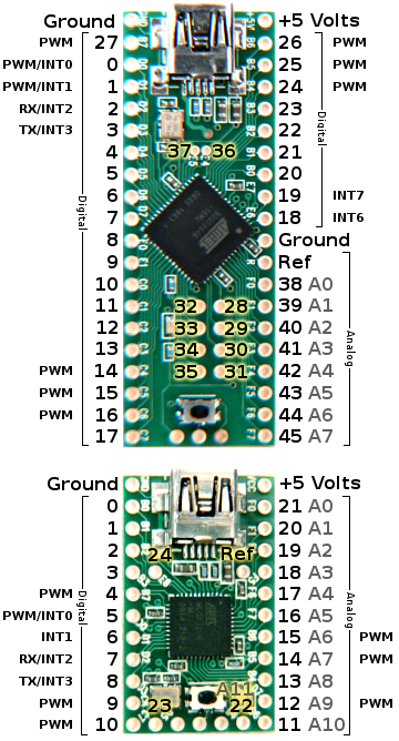
 16. Place the Teensy microcontroller on the breadboard.
 17. Connect ground on the Teensy to pin 8 of the left controller connector
 18. Connect Teensy digital pin 0 to pin 1 of the left controller connector
 19. Connect Teensy digital pin 1 to pin 2 of the left controller connector
 20. Connect Teensy digital pin 2 to pin 3 of the left controller connector
 21. Connect Teensy digital pin 3 to pin 4 of the left controller connector
 22. Connect Teensy digital pin 5 to pin 1 of the right controller connector
 23. Connect Teensy digital pin 6 to pin 2 of the right controller connector
 24. Connect Teensy digital pin 7 to pin 3 of the right controller connector
 25. Connect Teensy digital pin 8 to pin 4 of the right controller connector
 26. Connect Teensy digital pin 4 to pin 6 of the left controller connector
 27. Connect the breadboard to the Atari 2600
 28. Insert the programmable cartridge and make music!
Example Atari 2600 Cartridge:

Demo Videos
Demonstration of A26F interface
Sequencing and changing notes and instrument sounds
Sequencing drum samples and changing sample rate of playback
Quick Start Instructions
This post marks the release of the Atari 2600 MIDI (A26F) device, as well as the release of the A26F v100 firmware.
The code etc for this is open and free to use. Please do not commercialise this. It is not for making money. It is for making cool chiptune musics. I encourage you to build one of these. It is easy and shouldn't take long. I encourage you to hack the code and play and have fun with it. If you would like to make a batch of these available, please get in touch.
The aim of this post is to cover a simple hardware setup that can be used to create an A26F interface. This is achieved via an Atari Age 4K cartridge, a 2764 EPROM and a Teensy 2 microcontroller. Other methods are possible too.
- The A26F music interface relies on two pieces of firmware, one for a microcontroller and one for the Atari 2600 console.
- Download the firmware for the Atari 2600 console as a ROM here: http://little-scale.com/A26F/A26F_100/A26F_100_ROM.bin and as source code here: http://little-scale.com/A26F/A26F_100/A26F_Source_Code_6507.txt
- Upload the firmware ROM for the Atari 2600 console to a cartridge. Some suggestions on programmable cartridge solutions are made here:http://www.little-scale.blogspot.com.au/2013/03/current-options-for-atari-2600-user.html
- Download the firmware source code for the Teensy microcontroller here: http://little-scale.com/A26F/A26F_100/A26F_Teensy_100.ino
- Upload the firmware source code to the Teensy using the Arduino IDE (http://www.arduino.cc/) and the Teensyduino add-on (http://pjrc.com/teensy/teensyduino.html)
- Make a circuit with the following connections:
- Atari 2600 Player 1 Pin 1 ---> Teensy Port B0 (digital pin 0)
- Atari 2600 Player 1 Pin 2 ---> Teensy Port B1 (digital pin 1)
- Atari 2600 Player 1 Pin 3 ---> Teensy Port B2 (digital pin 2)
- Atari 2600 Player 1 Pin 4 ---> Teensy Port B3 (digital pin 3)
- Atari 2600 Player 1 Pin 6 ---> Teensy Port B7 (digital pin 4)
- Atari 2600 Player 1 Pin 8 ---> Teensy Ground
- Atari 2600 Player 2 Pin 1 ---> Teensy Port D0 (digital pin 5)
- Atari 2600 Player 2 Pin 2 ---> Teensy Port D1 (digital pin 6)
- Atari 2600 Player 2 Pin 3 ---> Teensy Port D2 (digital pin 7)
- Atari 2600 Player 2 Pin 4 ---> Teensy Port D3 (digital pin 8)
- The joystick pinout for the Atari 2600 can be found here: http://old.pinouts.ru/Inputs/JoystickAtari2600_pinout.shtml
- The Teensyduino pinout can be found here: http://pjrc.com/teensy/wiring_pinout2.png
MIDI Mapping
• MIDI Channel 1 is Atari TIA Channel 1
• MIDI Channel 2 is Atari TIA Channel2
• Velocity is mapped to 16 steps of amplitude for each channel
• MIDI CC #1 sets the instrument type
• MIDI CC#11 can also set the volume (independent of the velocity)
• Pitches wrap every 32 MIDI notes, and every pitch on the Atari is playable
• MIDI Channel 2 for notes > 64 will trigger drum samples if instrument 0 is chosen.
Step-by-Step: A26F Interface
Parts needed:
• 2 x Atari 2600 or SEGA controller (for cable splicing)
• OR 2 x female DB9 connectors if you don't want to destroy perfectly good controllers! (recommended)
• Teensy 2 microcontroller
• 2 x Small strip / vero board
• 2 x 10 pin header (only 9 pins needed)
• USB A to mini B cable
• Atari 2600 console
• Atari 2600 programmable cartridge
• Breadboard, Breadboard jumpers
• Soldering iron, Solder, Soldering helping hands, Solder cleaner, Wire stripppers, Multi-meter
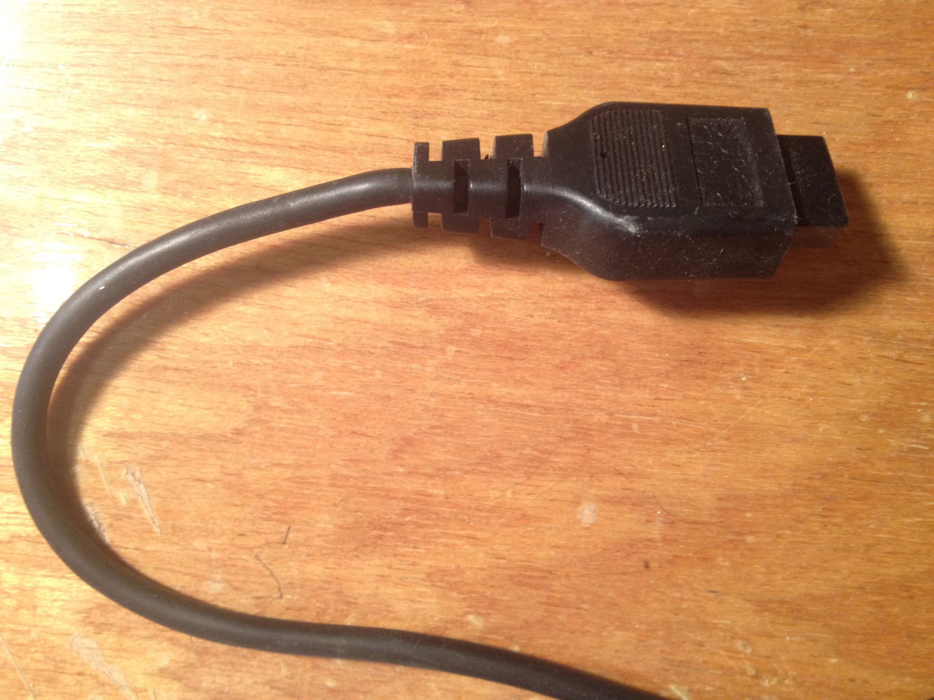
1. Take the Atari / SEGA controller and cut off the connector. Strip back the insulation.


10. Place the ten pin header in the board, so that each pin has its own vertical strip.


13. Repeat steps 1 - 12 so that there are 2 x pin header --> 9 pin connector cables


Example Atari 2600 Cartridge:

Atari Age 4K

5 comments:
Seb, You DA Man!
First vid blu me away. and the drum track, well I half to heat up the iron! Yogi
Hi Sebastian,
This is an excellent post! Thank you for sharing!
Forgive me if I'm a little bit slow, but I am having trouble finding the 2k/4k Atari 2600 PCB that you mention in your parts list. I found the Krokodile Cartridge and the Harmony Cartridge, but no raw 2k/4k PCB like the one you picture.
Would you mind providing a link to where I can buy one?
Thanks again for the awesome work!
All the best,
~G
I am getting a few errors while compiling which means I cannot acquire the hex version. I don't have a Teeny board, just an atmega32. I wish I knew how to correct these, but I am stuck asking for help.
Here are the errors:
A26F_Teensy_100.ino: In function 'void setup()':
A26F_Teensy_100:205: error: 'usbMIDI' was not declared in this scope
A26F_Teensy_100.ino: In function 'void loop()':
A26F_Teensy_100:234: error: 'usbMIDI' was not declared in this scope
-Jazzmarazz
Jazzmarazz,
The way to get rid of this is to either:
1) get a teensy and install the Teensyduino add on and the Teensy loader
OR
2) port this to Arduino proper
@ Gopal: I know that they are not currently being sold, BUT hopefully there will be on sale again at some stage.
Post a Comment